Yeah, that’s harsh, and you can accuse me of “punching down” and being a bully and a big old mean “elitist” (don’t get me started…), but I really couldn’t give a damn. Amateurs really suck – and much more now than ever. Look – I know that everyone has to start somewhere and you’ve got to learn and make mistakes and get better and all that, but something’s changed. These days people lack any kind of humility and feel compelled to share their ignorance and mediocrity endlessly with the world. We have failed in our collective responsibility to beat these people down. Instead of cooing over them, oo’ing and ah’ing over their abominations as you would your toddler’s macaroni artwork, point out that what they’re doing is wrong and it sets a bad example. In this touchy-feely society nobody want to hurt anyone’s feelings. If more people responded with “Why the fuck are you sharing this? I don’t give a shit and you’re lousy at it anyway, so just sod off”, we’d all have to put up with a lot less of this nonsense. And I’m so done with “makers”, but that’ll have to wait for a different rant. The point is that if you’re a neophyte, keep working on it and keep it to yourself until you have something worth sharing. This isn’t a brand-new idea; today our book club is going to assign Andrew Keen‘s “The Cult of the Amateur” (Doubleday, 2007).
It’s not a big deal – just some guy taking apart an old computer for a minor repair – but I’m cranky and started this blog to get this kind of shit out of my system. I ran across it because I’ve got the same machine (a Compaq SLT/286) and wanted to see if there were any tricks to it. There aren’t. You get a couple of screwdrivers – Torx 10 & 15 – and take out a whole bunch of screws to get to the PCB. Ain’t no magic. But Buddy felt compelled to lovingly, obsessively document this operation in a series of seventeen very sharp photographs (which he captions “Figures“, as if he’s writing a medical text), the way you see it done nowadays in endless recipes online: Here’s the bowl. Here’s the flour. Here’s the egg. Here’s me breaking the egg. Here’s the milk. Here’s the sugar. Here’s the baking powder. (If you’re counting, you should be at seven pictures). Now watch as I put each one in the bowl. Oopsie, spilled some – here’s the towel I’m wiping it up with. Now I’m mixing them. Now I’m going to pour the batter into the pan. And here’s my oven. You don’t have a gun in there, do you? ’cause if you do, please kill me now rather than subject me to more of this fucking agony. Listen: Your mom didn’t need anything more than a hand-written 3×5 index card in her recipe box, and neither do you.
But back to the computer. All this was just an introduction to the main course, which is reviving the Dallas Semiconductor DS1237 RTC/RAM chip. These things go back to the mid-80s; the idea of building the battery and supervisory circuit into the same package as the chip originally came from MOSTEK, and Dallas spun off the idea and ran with it. Makes things easy for us designers – before that I used Motorola’s MC6818, which is basically the same thing, just without the built-in battery – and it could be a little tricky. Anyway, the point is that the battery eventually runs down and the part has to be replaced. Without getting into a whole thing about “planned obsolescence” (really, please stop bitching, because in this business who expects a PC to be in service for more than a decade?), and though it takes rather more skill to do it than to change the battery on your average motherboard, it’s not something out of the reach of mere mortals.
But once inside, did he replace the part in question? No. Instead, afraid to pull the chip from the PCB, he gnawed at the 1287’s package like a rat until he hit metal and hacked on an external battery in the ugliest possible fashion (someone else’s idea, apparently). I’ve worked under some very trying conditions, and appreciate that there are times when you have to do things like this, but I strongly suspect that the comfortable environs of his tropical photo studio do not qualify. More importantly, though, it’s not something to be proud of. Show some spine. Get in there and do the job properly, and if you can’t, for chrissakes keep it to yourself, coward. Really, dude, we’re not talking about reworking fine-pitch SMT here. I happened to have an NOS 1287 in my Dallas bin, so I didn’t have to consider any of that nonsense. The new parts have a very good shelf life, too, because the battery isn’t connected to the clock and RAM until the software initializes the part. Go read the data sheet – you can download it in an instant, unlike the Old Days when you had to have the book.
The reality is, after you’ve extracted the board, desoldering this part is significantly easier than it is with an average plastic DIP, for an specific reason: PDIPs are fabricated with their pins (legs) not exactly vertical, but splayed out something like 7°. This is done to aid in the assembly process: The pins are squeezed vertical during the (through-hole) insertion process, and once released in the PCB holes the pins spring back out again and retain the part in the board through the remainder of the assembly process (soldering). If done properly, you can even turn the board over and hand-solder them without the chips falling out. But this has the downstream disadvantage of making the chips harder to desolder and remove from the board, because the pin pushing against the hole plating traps solder, making it a little tricky to separate pin from plating and increasing the chances of damaging the board (that’s why you see chickenshits without any skills chop the IC package free of the pins, then pick out the pins one at a time). The Dallas parts, however, are potted assemblies (rather than a conventional lead frame moulded into epoxy), and the pins are absolutely vertical, so even with basic hobbyist equipment it’s easy to suck out all the solder and have the part literally drop out of the board.
(Memo to Buddy: That Wahl Iso-Tip you’re using is simply not up to the job. That’s a child’s soldering iron – I know, because I used one when I was a child, before I developed skillz. Your little rechargeable iron takes too much time to heat up and the tip doesn’t have the mass necessary to keep its temperature during the desoldering operation. You want to run a Weller WTCPx iron, and go with a hot (i.e. 800°F), high-mass tip so you have the heat reserve to desolder the pin quickly – it’s lingering at too low a temperature that’s going to make the job hard and trash the board. Add an Edsyn DS-017 Soldapullt and you’re made in the shade.)
Now comes the cool part: I don’t ever want to have to go through all this again. So once the RTC was out, I soldered in a high-quality low-profile machined-pin socket. “But”, you say, “this is a tight assembly and there isn’t clearance above the part to accommodate the socket – the chip is going to butt up against the metalwork overhead.” And you’re right, so I cut a hole in the metal, and if it ever needs to be replaced again I don’t have to do anything more than remove the battery pack.
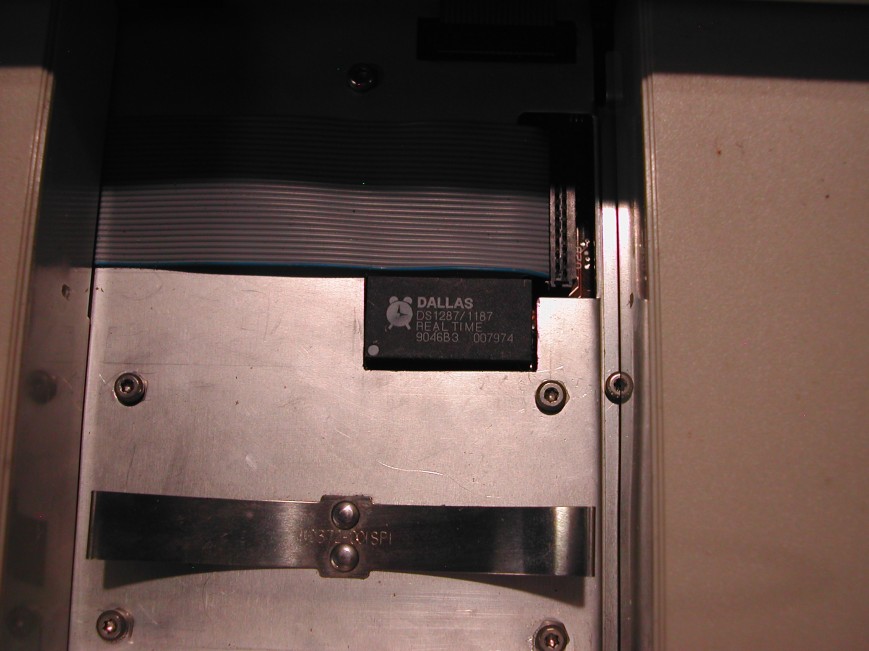
And here’s my shitty snap of the result, without any caption at all.
Cool, huh? Now you’re running with the big dogs.
